Home of The Shuttle...
Home The Cars The Humor Contact Me
Visitor Number
|
Welcome
to
TurboCelica.com.. Home of The Shuttle... |
Navigation
Menu Home The Cars The Humor Contact Me |
Visitor Number |
|
Chris' '90 Toyota Celica
All-Trac Turbo
(aka "The
Shuttle") Oil System Mods |
Updated: September 25, 2017 |
 During the switch to the CS hood and RC front
bumper, I've elected to make several changes to improve The Shuttle.
In the durability department, I've decided to implement a remote oil filter and
external oil cooler. Although I believe the stock oil cooler performs a
sufficient job of cooling oil on a stock engine, I have always felt Toyota
could have placed the oil filter further from the turbo system as it appears to
me it has the potential to absorb a significant amount of heat from the very hot turbo and down-pipe
assembly, which are located a mere inches away from the oil cooler and filter
assembly. As a result, I've purchase
a Setrab external oil cooler and remote oil filter mounts as well as fabricated
my own engine block adapter seen in the photos below.
During the switch to the CS hood and RC front
bumper, I've elected to make several changes to improve The Shuttle.
In the durability department, I've decided to implement a remote oil filter and
external oil cooler. Although I believe the stock oil cooler performs a
sufficient job of cooling oil on a stock engine, I have always felt Toyota
could have placed the oil filter further from the turbo system as it appears to
me it has the potential to absorb a significant amount of heat from the very hot turbo and down-pipe
assembly, which are located a mere inches away from the oil cooler and filter
assembly. As a result, I've purchase
a Setrab external oil cooler and remote oil filter mounts as well as fabricated
my own engine block adapter seen in the photos below.
During Tranny Swap Summer, I spent an entire weekend working out the engineering of the remote oil filter and oil coiling system... where to run the hoses. how to mount the filter mount to the fenderwell... angles of the fittings... everything... Let me know what you think.
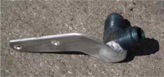
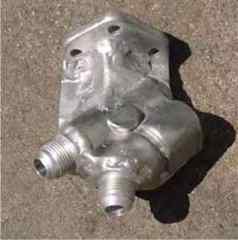
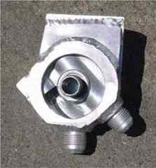
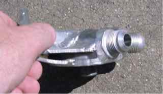
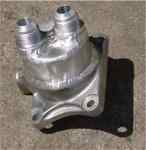  Engine Block Adapter.
Here's the adapter I fabricated to allow the use of
AN10 oil lines. As you can see, I modified the stock aluminum block mount
(upon which the stock oil/water cooler resides) with a large 2.375" outer
collar, an inner .5" ID aluminum tube, and two male AN10 fittings. Easy
and simple. Once it's mounted on the engine, I'll insulate it and
the oil lines with high-temp insulation to prevent heat absorption from
the nearby turbo and exhaust assembly. With this block adapter, 45 deg
fittings allow the hoses to snake under the alternator very cleanly. Engine Block Adapter.
Here's the adapter I fabricated to allow the use of
AN10 oil lines. As you can see, I modified the stock aluminum block mount
(upon which the stock oil/water cooler resides) with a large 2.375" outer
collar, an inner .5" ID aluminum tube, and two male AN10 fittings. Easy
and simple. Once it's mounted on the engine, I'll insulate it and
the oil lines with high-temp insulation to prevent heat absorption from
the nearby turbo and exhaust assembly. With this block adapter, 45 deg
fittings allow the hoses to snake under the alternator very cleanly. |
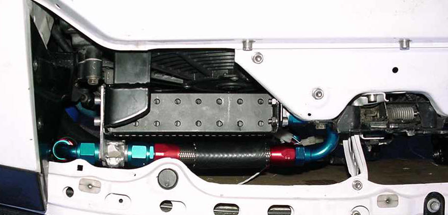
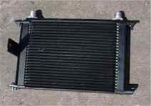
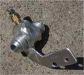
Oil Cooler and SS Hose Mounts. Here are photos of the Setrab oil cooler, and a couple hose stays I fabbed to keep the SS hoses secure. The brass fitting is the oil temp sender.
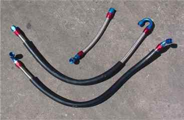
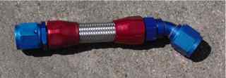
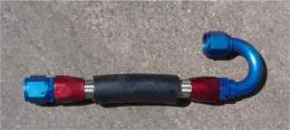
Oil Lines. All lines were fabricated with AN10 Earl's stainless steel hose. During assembly of the hoses, I run these stainless steel hoses inside a larger 1.25" ID rubber hose to reduce if not eliminate the ability of the stainless steel hoses to gently saw their way through whatever they rub against.
 |
  |
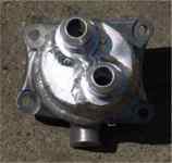
 Remote Oil Filter Mounts.
Here's
one very customized oil filter mount. :-) This part started life as a PermaCool remote oil filter mount. But, due to the limited space
under the hood of the GT4, I bastardized this part to make it fit the way I
wanted. In these photos, you can see that I took great care to
position the weld-on AN10 fittings at convenient angles. I basically
cut-off the portion which mounts to the fender and then just focused on
placement of the oil filter itself. I then carved-up a couple AN10 weld-on
fittings and the chunk of alum onto which the oil filter mounts. This
allowed me to slowly fit everything together till the hoses would attach without
forcing them into some bizarre angle - hence the slight upward and downward
angles on the AN10 fittings. Then, I started assembling hoses.
And, once they were in place, I bolted the alum part I had previous cut-off...
bolted it to the fender, and started fitting a couple aluminum plates to use in
welding each of the two pieces back together. Sounds simple, huh?
Trust me, it was far from simple. Engineering this remote oil filter and
cooling system was a big case of the chicken and the egg. Everything...
mount locations, hoses, hose ends, etc.. has to come together at the same time.
it's not like there's an abundance of room under the hood for a more simplistic
approach. Ain't aluminum great?!?! Everyone needs to
make friends with someone who owns a TIG welder, and, really knows how to use it!
Remote Oil Filter Mounts.
Here's
one very customized oil filter mount. :-) This part started life as a PermaCool remote oil filter mount. But, due to the limited space
under the hood of the GT4, I bastardized this part to make it fit the way I
wanted. In these photos, you can see that I took great care to
position the weld-on AN10 fittings at convenient angles. I basically
cut-off the portion which mounts to the fender and then just focused on
placement of the oil filter itself. I then carved-up a couple AN10 weld-on
fittings and the chunk of alum onto which the oil filter mounts. This
allowed me to slowly fit everything together till the hoses would attach without
forcing them into some bizarre angle - hence the slight upward and downward
angles on the AN10 fittings. Then, I started assembling hoses.
And, once they were in place, I bolted the alum part I had previous cut-off...
bolted it to the fender, and started fitting a couple aluminum plates to use in
welding each of the two pieces back together. Sounds simple, huh?
Trust me, it was far from simple. Engineering this remote oil filter and
cooling system was a big case of the chicken and the egg. Everything...
mount locations, hoses, hose ends, etc.. has to come together at the same time.
it's not like there's an abundance of room under the hood for a more simplistic
approach. Ain't aluminum great?!?! Everyone needs to
make friends with someone who owns a TIG welder, and, really knows how to use it!
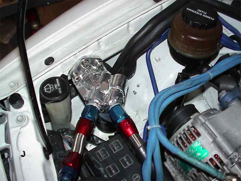
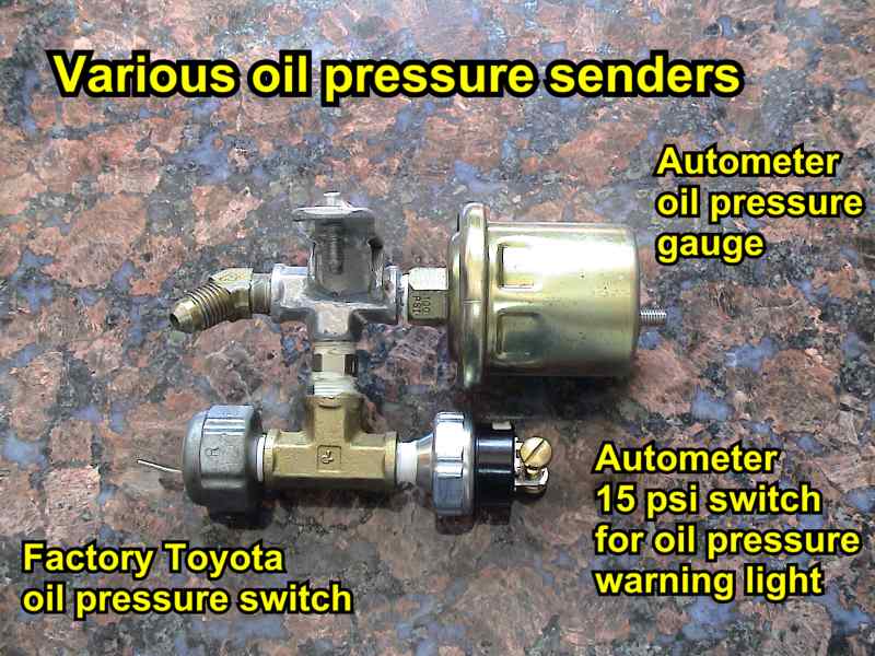 Oil
Pressure Instrumentation.
The Shuttle also utilizes a pair of Autometer
components to ensure oil pressure remains withing safe operating specs.
A 2" electric gauge provides real-time pressure information, and a Pro-Comp
warning light mounted to the A-pillar illuminates when oil pressure drops
below 15 psi. Below is an image of the manifold built to retain the
various oil pressure sending units, and more details are available on the
Instrumentation page. Oil
Pressure Instrumentation.
The Shuttle also utilizes a pair of Autometer
components to ensure oil pressure remains withing safe operating specs.
A 2" electric gauge provides real-time pressure information, and a Pro-Comp
warning light mounted to the A-pillar illuminates when oil pressure drops
below 15 psi. Below is an image of the manifold built to retain the
various oil pressure sending units, and more details are available on the
Instrumentation page.The Shuttle also utilizes a custom crankcase ventilation catch-can. |
 |
 |
| This site is best viewed at 1024x768. All information provided on www.turbocelica.com is provided without any expressed or implied warranty. It is the responsibility of each visitor to determine the suitability of this information for your specific application. |